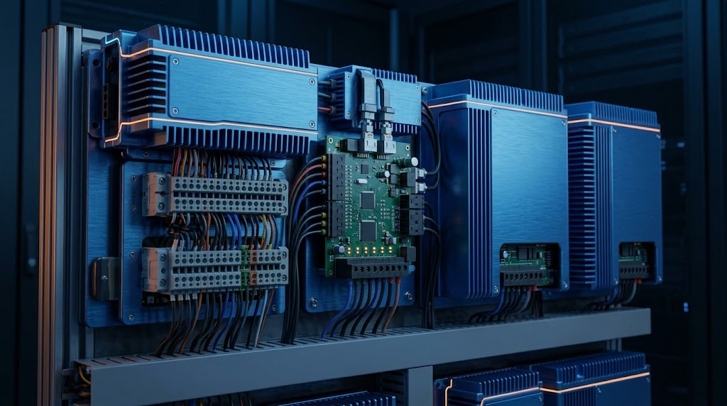
How to Prevent Voltage Drop in Long-Run LED Channel Letter Systems
In commercial signage, lightboxes, and long-run architectural channel letter installations, constant-voltage LED systems frequently encounter a technical issue: voltage drop. As direct current (DC) travels along extended copper conductors, line resistance causes potential to diminish. This results in uneven illumination, visible color shifting, and unexpected LED module flickering toward the far end of the installation.
This technical guide outlines the physical causes of voltage drop in commercial signage lighting, provides practical voltage calculation methods, and demonstrates how selecting high-capacity power units—such as the 250w indoor power supply—helps signage manufacturers maintain uniform brightness across long-distance installations.
Physics of Voltage Drop in LED Channel Letters
Voltage drop occurs when electrical resistance within copper wiring converts potential energy into heat before it reaches the LED load.
Power Source (24V DC) ─────► Copper Trace Resistance (R) ─────► Far-End LED (21.5V DC)
    [ Nominal Potential ]         [ Voltage Diminishes ]          [ Reduced Brightness ]
The Math Behind Conductor Loss
According to Ohm’s Law (), voltage loss along a cable depends on two primary variables: total current () and round-trip conductor resistance ().
-
: One-way distance of the cable run (meters).
-
: Total current drawn by connected LED modules (Amps).
-
: Electrical resistivity of copper.
-
: Cross-sectional area of the wire conductor ().
Higher current draw () and longer wire runs () accelerate potential drop. In 12V DC systems, current is twice that of 24V DC systems for identical wattage, making 12V channel letter runs significantly more susceptible to voltage decay.
Comparing 12V DC and 24V DC Signage Power Supplies
Selecting the correct operating voltage is one of the most effective strategies for preventing long-run potential loss.
+---------------------------------------------------------------------------------------------------+
|                                 12V DC vs. 24V DC System Performance                              |
+-------------------+-----------------------------------+-------------------------------------------+
| System Voltage    | Operating Current for 240W Load   | Susceptibility to Voltage Drop            |
+-------------------+-----------------------------------+-------------------------------------------+
| 12V DC System     | 20.0 Amps (Requires thicker wire) | High (Noticeable drop beyond 3-5 meters)  |
| 24V DC System     | 10.0 Amps (Lower current load)    | Low (Stable over 8-10+ meters)            |
+-------------------+-----------------------------------+-------------------------------------------+
Switching channel letter array designs to a 24V architecture cuts line current in half. Deploying a regulated 250w indoor led driver 24v 10.4a ip20 allows signage fabricators to double the maximum run length of illuminated letter strings while maintaining uniform current across every LED module.
Four Wiring Strategies to Eliminate Voltage Decay
Signage installers can mitigate potential loss across complex channel letter arrays using standard wiring layout methods:
Strategy 1: Parallel Feed     ──► Splitting main supply into multiple parallel branch runs.
Strategy 2: Ring Feed         ──► Connecting both ends of the run back to the power supply.
Strategy 3: Center Feed       ──► Feeding power into the midpoint of the LED array string.
Strategy 4: Remote Sensing    ──► Adjusting terminal voltage to compensate for cable line loss.
Midpoint Feeding (Center Feed)
Instead of feeding power from one end of a channel letter string, connect the output cable from an indoor led driver ip20 to the middle of the run. This cuts the effective length of the run in half, reducing voltage drop by up to 75%.
Parallel Home-Run Wiring
For large cabinet signs or individual channel letters, avoid daisy-chaining modules in a single series line. Run separate parallel wire leads from the power supply terminal block to smaller sub-groups of letters.
Power Supply Selection and Capacity Sizing
Sizing power supplies correctly ensures stable voltage delivery and prevents thermal shutdown during continuous operation.
+---------------------------------------------------------------------------------------------------+
|                                  Driver Loading and Cable Sizing Matrix                          |
+---------------------+---------------------+----------------------+--------------------------------+
| Target LED Load     | 80% Safety Margin   | Required Driver Size | Recommended Cable Gauge (AWG)  |
+---------------------+---------------------+----------------------+--------------------------------+
| 100 Watts           | 125 Watts           | 150W 24V Unit        | 18 AWG                         |
| 200 Watts           | 250 Watts           | 250W 24V 10.4A Unit  | 14 AWG - 16 AWG                |
| 400 Watts           | 500 Watts           | Dual 250W Units      | 12 AWG - 14 AWG                |
+---------------------+---------------------+----------------------+--------------------------------+
Always calculate continuous load requirements using the 80% Rule:
Connecting a 200W LED array to a high-output unit like a 250w indoor power supply provides necessary thermal headroom, stabilizing output potential even during outdoor ambient heat fluctuations.
Field Troubleshooting Checklist for Signage Installers
[Diagnostic Process for Dim Channel Letters]
       │
       ├──► First Modules Bright, Far Modules Dim? ──► [Issue: Cable Resistance. Solution: Add Midpoint Feed]
       │
       ├──► All Modules Pulsing / Strobing?       ──► [Issue: Overload Protection. Solution: Verify 80% Load]
       │
       └──► Color Temperature Drift Across Array?   ──► [Issue: Low Operating Voltage. Solution: Upgrade to 24V]
When inspecting completed lightbox or channel letter installations, use a digital multimeter to measure output potential at both the power supply terminal block and the final LED module in the chain. Ensure the total potential drop from feed to tail does not exceed 5% of nominal system voltage.
Summary & Installation Checklist
Preventing voltage drop in commercial signage installations requires proper wire sizing, correct voltage selection, and reliable driver technology.
Signage Installer’s Action List
-
Select 24V DC Architecture: Use 24V systems for long runs to reduce overall current draw.
-
Apply the 80% Load Rule: Keep total module wattage under 80% of rated driver capacity.
-
Implement Parallel Feeds: Avoid long single-series daisy chains; split arrays into parallel home runs.
-
Verify Driver Specifications: Deploy reliable power supplies like the 250w indoor led driver 24v 10.4a ip20 to maintain stable voltage delivery.
For detailed electrical schematics, form factors, and technical documentation, check the official 250w indoor led driver 24v 10.4a ip20 product page.