Understanding Constant Voltage vs. Constant Power in LED Supplies
Selecting the correct power drive architecture is one of the most vital engineering decisions when designing commercial LED systems, architectural lighting fixtures, and industrial illumination networks. Lighting specifiers, electrical engineers, and B2B buyers frequently face a critical technical choice: Constant Voltage (CV) versus Constant Power (CP) LED power supplies.
Selecting the wrong topology can lead to premature phosphor degradation, thermal runaway, uneven light distribution across long runs, or unexpected fixture failure. This technical manual explores the functional differences, load dynamics, efficiency curves, and ideal B2B application scenarios for both systems.
Electrical Fundamentals: Constant Voltage vs. Constant Power
Understanding how power supplies regulate output parameters under varying load conditions is essential for matching the driver to your specific fixture architecture.
+---------------------------------------------------------------------------------------------------+
|                                  Driver Topology Comparison                                       |
+-------------------+----------------------------+-----------------------------+--------------------+
| Topology          | Voltage Output             | Current Output              | Key Characteristic |
+-------------------+----------------------------+-----------------------------+--------------------+
| Constant Voltage  | Fixed (e.g., 24V DC)       | Dynamic (Scales with load)  | Parallel Circuits  |
| Constant Power    | Dynamic (Adjusts inversely)| Dynamic (Adjusts inversely) | Constant Wattage   |
+-------------------+----------------------------+-----------------------------+--------------------+
Constant Voltage (CV) Architecture
A Constant Voltage supply maintains a stable, pre-determined output voltage (typically 12V DC or 24V DC) regardless of current load fluctuations, provided the total load does not exceed the driver’s maximum wattage rating.
-
Circuit Configuration: Loads are wired in parallel.
-
Operational Behavior: As more LED modules or strip segments are added in parallel, the total resistance decreases, causing the supply to automatically deliver higher total current while keeping the output voltage locked at 24V.
Constant Power (CP) Architecture
A Constant Power supply dynamically regulates both output voltage and current in real time to keep total output power () constant across a designated operating window.
-
Circuit Configuration: Flexible; widely used in high-bay, stadium, and industrial fixtures.
-
Operational Behavior: If the forward voltage () of the LEDs changes (e.g., due to thermal shifts), the driver automatically scales current output in reverse proportion to maintain continuous full-wattage operation without overdriving the diodes.
Voltage Drop and Current Regulation in Long-Run Systems
In commercial installations—such as architectural cove lighting or building perimeter outlines—strip runs frequently extend past 10 meters. Physical conductor resistance becomes a major failure point in these setups.
Managing Voltage Drop in Parallel CV Systems
Copper traces on printed circuit boards (PCBs) act as resistors. As current flows down an extended LED strip, voltage gradually drops ().
-
12V vs. 24V Considerations: A 24V system requires half the current of a 12V system to deliver the same power (). Lower current cuts voltage drop by half, reducing brightness decay along long runs.
-
High-Amp Slim Solutions: Using high-density industrial units like the Sanpu PS250-H1V ensures that nominal 24V DC potential is maintained at the feed line, preventing early-segment thermal stress.
Power Feed (24V DC) -------------> Cable Resistance (R) -------------> Strip End (22.8V DC)
      [ Stable Input ]               [ Minimal Amps = Low Drop ]        [ Uniform Illumination ]
Thermal Drift and Compensation Mechanisms
LED forward voltage () drops as junction temperatures rise—a phenomenon known as the negative thermal coefficient.
-
CV Systems Reaction: In a constant voltage setup, a drop in across fixed-value onboard resistors causes current draw to rise slightly. If thermal dissipation is inadequate, this can trigger a feedback loop known as thermal runaway.
-
CP Systems Reaction: Constant power drivers mitigate thermal risks by continuously sampling current and voltage. When internal LED junction heat causes to drop, a constant power driver lowers output current proportionally to keep total wattage stable. This extends component lifespan in sealed high-temperature enclosures.
Efficiency Curves and Load Optimization
Operating a driver outside its optimal load window increases wasted heat energy and lowers overall system power factor (PF).
+---------------------------------------------------------------------------------------------------+
|                                Load Efficiency & Thermal Characteristics                           |
+------------------+---------------------+-----------------------+----------------------------------+
| Operating Load   | System Efficiency   | Power Factor (PF)     | Thermal Generation               |
+------------------+---------------------+-----------------------+----------------------------------+
| < 30% Load       | Low (60% - 75%)     | Poor (< 0.70)         | High Idle Thermal Dissipation    |
| 50% - 70% Load   | Moderate (80% - 85%)| Acceptable (> 0.88)   | Stable Operating Temp            |
| 80% - 90% Load   | Peak (88% - 94%)    | Optimal (> 0.95)      | Efficient Thermal Dissipation    |
+------------------+---------------------+-----------------------+----------------------------------+
To maintain an active Power Factor () and comply with commercial grid standards, select driver capacities where the calculated peak continuous draw sits squarely within the 80% to 90% range of rated capacity.
Application Scenarios: Choosing the Right Driver Topology
Selecting the ideal drive topology depends directly on your fixture design and wiring scheme.
When to Use Constant Voltage (CV)
-
Architectural Linear Strips: Parallel cuttable LED tapes, thin flex strips, and aluminum extrusion channels.
-
Cabinet and Signage Backlighting: Modular channel letters where individual modules are regularly added or removed in parallel.
-
Low-Profile Interior Enclosures: Spaces requiring ultra-slim form factors like the Sanpu PS250-H1V Datasheet for concealed dry-location mounting.
When to Use Constant Power (CP)
-
Industrial High-Bay Fixtures: Factory lighting where operating temperatures fluctuate across wide ranges.
-
Modular OEM Luminaire Manufacturing: Single fixture designs intended to support multiple current configurations without replacing internal drivers.
-
High-Output Outdoor Floodlights: High-wattage arrays requiring dynamic thermal adjustment during summer ambient peak temperatures.
Diagnostic Flowchart for Electrical Troubleshooting
When diagnosing power supply issues in commercial installations, follow this systematic diagnostic sequence:
[Issue: System Malfunction]
       │
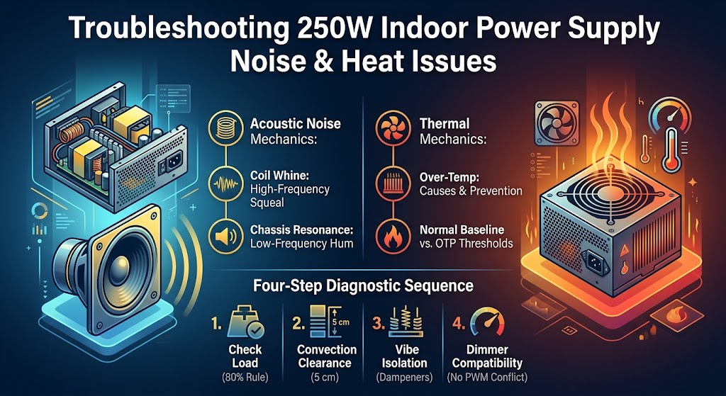
       ├──► LEDs Pulsing / Flashing? ──► [Check: Load Exceeds 80% Limit or OTP Tripped]
       │
       ├──► Dimming Near End of Run?  ──► [Check: Gauge Resistance / Voltage Drop; Upgrade to 24V]
       │
       └──► Driver Running Hot?       ──► [Check: Ventilation Clearance (Min 5 cm) & Airflow]
Quality Standards and Technical Specification Checklist
Industrial B2B procurement demands strict adherence to safety certifications and manufacturing specs.
B2B Component Quality Standards
-
Electromagnetic Interference (EMI) Mitigation: Built-in Class B EMC filtering prevents RF interference with nearby Wireless Access Points (WAPs) or control systems.
-
Capacitor Thermal Class: Internal electrolytic capacitors rated for 105°C operation yield significantly longer lifespan than standard 85°C consumer components.
-
Short Circuit & Over-Current Protection: Auto-recovery protective circuits isolate faulty parallel branches without permanently damaging the primary switching transformer.
Summary & Technical Procurement Checklist
Matching drive topology accurately to your fixture design avoids costly field retrofits and failure rates.
B2B Engineer Procurement Checklist
-
Verify Circuit Topology: Confirm whether LEDs require parallel CV feeds or series CP drive adjustment.
-
Calculate Cable Loss: Size secondary wire gauges appropriately to ensure full potential reaches terminal runs.
-
Apply the 80% Safety Margin: Verify that continuous operating load does not exceed 80% of total rated output power.
-
Review Physical Specs: Ensure physical driver dimensions fit within architectural light channel cutouts.
For complete mechanical dimensions, thermal curves, and electrical load specs on commercial slim power supplies, download the full Sanpu PS250-H1V Datasheet to complete your project submittals.