Custom Power Supply Design Guide: Key Factors for Space-Constrained Industrial Electronics
Standard off-the-shelf (COTS) switching power supplies often fail to meet the spatial, thermal, and electrical constraints of specialized industrial equipment. When designing compact enclosures for medical devices, automated test equipment, low-profile display signage, or high-density server racks, power density ($\text{W/in}^3$) and custom form factors become critical design bottlenecks.
This engineering guide details the primary parameters, thermal management topologies, and procurement evaluation criteria for specifying a Custom Power Supply Solution for space-restricted industrial applications.
1. Defining Mechanical Constraints: Enclosure Form Factors and Power Density
In space-constrained electronics, mechanical housing design dictates circuit board layout and component selection. Integrating custom AC/DC power supplies into tight chassis spaces involves evaluating three key mechanical parameters:
Space-Constrained Chassis Design Trade-Offs

┌─────────────────────────┐      Higher Thermal Density
│ Compact Physical Volume │ ─────────────────────────────► Requires Conduction Cooling
└─────────────────────────┘                                 or Aluminum Heat Sinks
             │
             │ High Components Density
             ▼
┌─────────────────────────┐      Requires Custom PCB Layout
│  Custom Height Profile  │ ─────────────────────────────► Low-Profile Inductors &
│   (e.g., 1U / 25mm)     │                                Flat Transformers
└─────────────────────────┘
-
Vertical Height Profile (Z-Axis Limits): Standard enclosed industrial drivers typically feature profile heights between $38\text{mm}$ and $50\text{mm}$. Custom space power supply designs reduce overall height down to $25\text{mm}$ or less (1U rack compatibility) by utilizing planar transformers, low-profile electrolytic capacitors, and custom-wound inductors.
-
Volumetric Power Density ($\text{W/in}^3$): Pushing power density above $15\text{W/in}^3$ requires transition from legacy flyback or forward topologies to high-frequency LLC resonant converters paired with Silicon Carbide (SiC) or Gallium Nitride (GaN) switching transistors.
-
Custom Mounting Hole Topology & I/O Terminals: Custom designs allow engineers to locate AC input terminal blocks, DC output busbars, and signal headers precisely aligned with chassis cutouts, eliminating external wiring harnesses and reducing internal assembly labor.
2. Electrical Customization Matrix: Beyond Standard Voltage Rails
Off-the-shelf power supplies offer standard fixed outputs ($12\text{V}$, $24\text{V}$, $48\text{V}$). However, complex industrial systems often require multi-rail outputs, wide trim ranges, or customized current-limiting curves.
| Custom Specification | Engineering Options & Implementation | Target Application |
| Non-Standard Output Rails | Custom secondary transformer windings delivering precise voltages (e.g., $18\text{V}$, $36\text{V}$, or dual $\pm15\text{V}$ rails). | Laser drivers, piezo actuators, audio amplifiers. |
| Wide Output Voltage Trimming | Potentiometer or digital $0\text{–}10\text{V}$ control adjusting output over $30\text{–}115\%$ of nominal rating. | Battery charging, motor speed control, LED dimming. |
| Current Foldback & Constant Current | Dual-mode Constant Voltage / Constant Current (CV/CC) limiters. | Inductive load drives, battery back-up charging. |
| Auxiliary Output Rails | Independent standby rail ($5\text{V}_{\text{sb}}/1\text{A}$) powering microcontrollers while primary power stage slumbers. | IoT industrial controllers, remote wake-up nodes. |
A specialized Custom Power Supply Manuacturer (custom industrial power supply design)can integrate continuous telemetry signals—such as Power Good (P-OK), Remote Sense, and $I^2C$ / PMBus monitoring—directly onto the power board, allowing host systems to track operating temperature, load current, and input line quality in real time.
3. Thermal Management Topologies in Sealed and Space-Restricted Spaces
Heat dissipation is the leading cause of electrolytic capacitor failure in compact power units. When designing power supplies for sealed IP-rated enclosures or zero-airflow environments, engineers must select thermal transfer methods suited to ambient operating conditions:
1. Convection Cooling (Perforated Enclosures)
-
Mechanism: Relies on natural upward air movement through vented aluminum mesh.
-
Best Used For: Internal equipment bays with ambient temperatures below $45^\circ\text{C}$ and existing airflow clearance.
-
Limitation: Cannot be used in dusty, humid, or conductive particle environments.
2. Conduction Cooling (Cold-Plate Mounting)
-
Mechanism: Heat-generating components (MOSFETs, bridge rectifiers, output diodes) couple directly to a thick aluminum baseplate via thermal interface materials (TIM). The baseplate mounts flat against the customer’s external metal chassis, turning the machine housing into a primary heatsink.
-
Best Used For: Sealed industrial PCs, outdoor displays, and tight space-constrained equipment modules.
-
Advantage: Eliminates noisy cooling fans and reduces internal ambient temperatures by up to $15^\circ\text{C}$.
3. Forced Air Cooling (Internal Micro-Fans)
-
Mechanism: Integrated temperature-controlled fan blowing air directly across internal heat sinks.
-
Best Used For: High-wattage density applications ($>400\text{W}$) in restricted enclosures where chassis conduction cooling is impossible.
4. Electromagnetic Compatibility (EMC) and Isolation Engineering
Space-constrained power supply designs present intense electromagnetic interference (EMC) challenges due to the close proximity of switching components to low-voltage signal processing circuitry.
EMC Suppression Pipeline

[Raw AC Line Input]
        │
        ▼
[Custom 2-Stage Differential & Common Mode Line Filter]
        │
        ▼
[Faraday Shielding Screen around High-Frequency Transformer]
        │
        ▼
[Zero-Voltage Switching (ZVS) Resonant Topology]  <-- Reduces dV/dt Switching Noise
        │
        ▼
[Filtered Low-Noise DC Output Terminal]
To meet EN 55032 / FCC Part 15 Class B radiated and conducted emission limits without adding bulky external filters:
-
Integrated Multi-Stage Common-Mode Chokes: Custom input stage layouts incorporate high-permeability nanocrystalline core chokes engineered to dampen high-frequency switching noise.
-
Transformer Interlayer Shielding: Copper foil shields placed between primary and secondary transformer windings divert capacitive displacement currents directly to primary ground before reaching the DC output rail.
-
Optocoupler and Digital Isolation: Galvanic isolation between primary switching control and output feedback circuits guarantees safety insulation ratings up to $3000\text{V AC}$ (or $4000\text{V AC}$ for medical grade compliance).
5. B2B Custom Engineering Process: From Concept to Mass Production
Executing a custom industrial power supply project requires clear milestones between the equipment manufacturer (OEM) and the power design team to avoid costly iteration delays.
Key OEM Customization Milestones

Phase 1: Requirements Specification (RFP)
  ├── Define physical envelope dimensions & mounting hole locations
  └── Outline input/output voltage, ripple limits, and operating ambient temp

Phase 2: Prototyping & Thermal Modeling
  ├── 3D CAD modeling & thermal simulation analysis
  └── Functional bench testing of 3D-printed/hand-built prototypes

Phase 3: Compliance & Pre-Certification
  ├── Conducted/Radiated EMI pre-scans
  └── Safety isolation & thermal stress burn-in testing (100% load at 50°C)

Phase 4: Tooling & Mass Production
  ├── Automated SMT assembly line setup
  └── Final automated test equipment (ATE) testing for 100% produced units
6. Custom vs. Standard Power Supply Decision Matrix
Evaluating whether a project warrants a custom ground-up design or can utilize a modified standard power supply depends on annual production volume and design constraints:
| Evaluation Factor | Modified Standard Supply | Full Custom Power Supply |
| NRE (Non-Recurring Engineering) Cost | Low to Moderate ($500 – $2,000) | Moderate to High ($5,000 – $20,000+) |
| Development Lead Time | 3 to 6 weeks | 10 to 16 weeks |
| Minimum Order Quantity (MOQ) | 100 – 500 units | 1,000+ units |
| Mechanical Fit Efficiency | Moderate (May require adapter plates) | 100% Optimized to chassis CAD model |
| Unit Production Cost | Baseline | 15% to 30% lower at high volumes |
| Agency Certification Path | Uses existing safety family approvals | Requires standalone safety/EMC submittal |
Engineering Guidance: If your project volume exceeds 1,000 units annually or requires mounting within non-standard enclosures with strict thermal and EMC targets, full custom development delivers lower per-unit costs and eliminates secondary conversion stages.
Project Procurement Checklist
When submitting a Request for Quotation (RFQ) for custom switching power supplies, supply your manufacturing partner with these baseline technical parameters:
-
Target Envelope Dimensions: Length $\times$ Width $\times$ Height (including connector clearance limits)
-
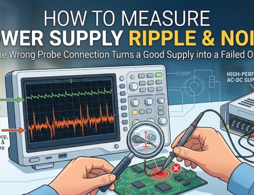
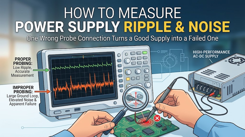
Electrical Parameters: Input AC range, nominal DC outputs, maximum peak load current, ripple/noise thresholds
-
Thermal Environment: Maximum ambient temperature, available airflow (LFM), chassis conduction surface area
-
Required Certifications: CE, UKCA, UL/cUL 62368-1 (Industrial) or IEC 60601-1 (Medical)
-
Target Annual Volume & Target Unit Price
To start a custom engineering evaluation or submit your 3D CAD enclosure models for thermal feasibility analysis, consult the engineering specialists at our Custom Power Supply Solutions center or submit your technical specifications directly through our engineering contact portal.