Constant Current vs Constant Voltage vs Constant Power LED Drivers: Pick the Wrong Mode and the Whole Batch Comes Back
A project reworked 1,200 luminaires. Not because the LEDs failed and not because the drivers failed — because procurement ordered “250 W constant power drivers” and the installed fixtures only strung up to 24 V.
The drivers never faulted. They were working exactly as designed. They just never produced 250 W at that voltage. Measured output was 171 W, and the fixtures ran at roughly 70% of design brightness. Nobody noticed until everything was installed, and then 1,200 fixtures came back down.
Failures like this aren’t rare in LED lighting, because the problem hides somewhere unremarkable: the power number on a driver nameplate comes with a precondition. This article covers how the three output modes differ on a V-I plot, what that precondition actually is, and where the traps sit.
Three modes, three different curves
Put output voltage on the horizontal axis and output current on the vertical, and the three modes draw three different shapes.
Constant voltage (CV)
Usually 12 V or 24 V. Output voltage is locked at the nominal value regardless of load, and the current is whatever the load draws — up to the driver’s maximum current rating.
LED strip can be connected straight to a CV supply because the strip carries its own current limiting: series resistors or linear constant-current ICs built into the tape. The supply’s job is to hold a stable voltage. Current limiting belongs to the strip.
Used for: LED tape, profiles, channel letters, modular signs, any finished luminaire with built-in limiting. Our constant voltage power supply line and the constant voltage dimmable range both sit in this category.
Constant current (CC)
The reverse. Output current is locked, and voltage adapts within a window. The nameplate reads something like “700 mA, 18–36 V” — meaning it will deliver 700 mA, and where the voltage lands inside that 18–36 V band depends on how many LEDs you strung.
That 18–36 V is the compliance voltage window. Six LEDs in series at roughly 3 V each is 18 V; twelve is 36 V. Outside the window the driver either shuts down on protection or behaves erratically.
Used for: spotlights, track lights, downlights, floodlights, horticultural fixtures — anything with bare LED strings.
Constant power (CP)
P = V × I held constant. Voltage goes up, current goes down; voltage drops, current rises. The product stays put.
Used for: one driver covering multiple LED string lengths. A luminaire platform with a 10-LED variant (≈30 V) and a 16-LED variant (≈48 V) can run one driver across both — single BOM line, half the inventory.
That’s the appeal. The trouble is in the word “constant.”
A constant power driver’s 250 W is not available across the whole voltage range
This is the most important section here, and it’s what caused the 1,200-unit rework.
Constant power isn’t an unbounded hyperbola — it’s a hyperbola clamped at both ends. Take a typical 250 W constant power driver with a window of 35–55 V:
| Load voltage | Output current | Actual output power | Operating region |
| 55 V (window upper limit) | 4.55 A | 250 W | Constant power |
| 48 V | 5.21 A | 250 W | Constant power |
| 35 V (window lower limit) | 7.14 A | 250 W | Constant power |
| 24 V (below window) | 7.14 A (clamped) | 171 W | Current limit |
| 60 V (above window) | 4.55 A (clamped) | 273 W → protection | Voltage limit |
At 24 V the driver drops into the current-limit region below the window: current is clamped at the maximum the window allows, 7.14 A, so output is 24 V × 7.14 A = 171 W — 68.6% of the nameplate.
Nothing is broken. Nothing even flags a fault. The driver is following its own rules. The luminaire is just 30% dimmer than specified.
One check before you order: compare your load voltage against the driver’s constant power window. Below the lower limit, actual power = load voltage × the window’s maximum current. Above the upper limit, the driver goes into overvoltage protection.
Most datasheets bury that window in “output current range” or in a small graph, nowhere near the headline number. If you can’t find it, ask for the V-I curve directly — one graph is cheaper than reworking 1,200 fixtures. The full selection procedure is in how to select a constant power LED driver, and the window is published on every unit in the constant power LED driver range.
Constant current drivers cannot be paralleled
“Same current, so parallel should be fine” is a natural assumption and completely wrong.
Two constant current sources in parallel each try to force their own rated current. They fight: one hits its voltage ceiling and goes into protection first, the other is left carrying the full current and follows it into protection. At best you get flickering and restart cycling. At worst both drivers hiccup repeatedly until something overheats.
The rule is simple:
- Constant current (CC) → loads in series
- Constant voltage (CV) → loads in parallel
It works in reverse too. If your luminaires are wired in parallel — several strips tied to one bus — you want a CV supply. If they’re a single series string, you want CC.
There’s one narrow exception: some CC drivers are documented as parallelable, usually because they carry current-sharing circuitry or are deliberately designed to sit on the CV boundary. That has to be stated explicitly in the datasheet. Never assume it.
24 V drops a quarter as much voltage as 12 V — but cuts in half as finely
Start with voltage drop, because it’s worth doing the arithmetic.
Loss is P = I²R. At the same power, a 24 V system carries half the current of a 12 V one, so it loses a quarter as much.
Concretely: a 10 m run of tape, 60 W total, 1.5 mm² copper (roughly 12 Ω/km, so about 0.24 Ω for 20 m out and back):
- 12 V system: 5 A, loss = 5² × 0.24 = 6 W, end-of-run drop 1.2 V (10%)
- 24 V system: 2.5 A, loss = 2.5² × 0.24 = 1.5 W, end-of-run drop 0.6 V (2.5%)
That’s why architectural lighting, landscape runs and long coves use 24 V or 48 V, and why 12 V is left to vehicles, display cases and other short runs.
The cost: 24 V tape has a cutting unit twice as long as 12 V.
White and blue LEDs run about 3 V forward each, so:
- 12 V tape: 3 LEDs plus one resistor per section → typically a 25 mm cut unit
- 24 V tape: 6 LEDs plus one resistor per section → typically a 50 mm cut unit
In narrow profiles, shaped lettering or small signage, a 50 mm minimum often won’t fit, and 12 V is the right call.
The decision rule: long runs (over 5 m) go 24 V. Fine cutting (under 50 mm units) goes 12 V. Need both? Run 24 V as the trunk and drop to 12 V for short end sections. On the 24 V side the 250 W indoor ultra-thin power supply IP20 is the usual choice for long architectural runs, and the voltage-drop arithmetic is worked through in 24 V LED driver power distribution.
Dimming: four interfaces, four different ways to get it wrong
Dimming is the other rework hotspot. The four mainstream options:
| Interface | Standard | Wiring | Common trap |
| 0–10 V | IEC 60929 Annex E | Two low-voltage wires, polarity matters | Source and sink variants; reverse them and it just won’t light |
| 1–10 V | Same standard (sink type) | Two low-voltage wires | 0 V doesn’t switch off — 1 V is minimum |
| DALI-2 | IEC 62386 | Two wires, polarity-free bus | Needs addressing and grouping; commissioning is real work |
| DMX512 | ANSI E1.11 (ESTA) | Differential pair with shield | Needs a terminator; long runs need repeaters |
| PWM | No single standard | Chopped output | Low frequency means visible flicker |
The specific traps:
Don’t mix 0–10 V source and sink. With source, the driver supplies a 10 V reference and the dimmer acts as a variable resistor. With sink, the dimmer supplies the voltage and the driver absorbs current. Wiring them backwards usually just results in no light — but on a large site, tracing it is expensive. Protocol behaviour across 0–10 V, DALI-2, DMX512 and PWM is set out in dimming protocols for constant power LED drivers.
1–10 V on a 0–10 V dimmer won’t go dark at 0 V. In the 1–10 V convention, 1 V is minimum brightness; 0 V was defined in the older spec as “signal lost,” and implementations disagree on whether that means full on or off. If you need a true blackout, either confirm the driver supports 0 V shutdown or put a relay on the AC side.
PWM frequency has to be high enough. Below 200 Hz the flicker is visible to the eye and shows up as banding on a phone camera. IEEE 1789 puts the no-risk region above about 1.25 kHz combined with under 8% flicker percentage. Plenty of low-cost PWM drivers run at 200–500 Hz, and working under that light for extended periods causes eye strain and headaches. Better dimmable drivers run 1–20 kHz.
DALI-2 needs commissioning. It isn’t wire-and-go. Every driver needs a short address, group assignment and scene setup. On a 200-luminaire project, DALI commissioning hours can exceed the wiring hours. What you get in return is per-luminaire addressing, status readback and fault reporting — worth it on large commercial jobs, not worth it on a small one.
Where the 20% headroom rule comes from
“Leave 20% on an LED driver” is standard advice that rarely gets explained.
Two reasons, and the second one matters more.
First — start-up and transients. LED forward voltage is lower when cold, so inrush current is higher; mains variation of ±10% moves input current too. Twenty percent covers those transients.
Second, and more important — electrolytic capacitor life. The shortest-lived part inside a driver is the output electrolytic. Apply the 10 °C rule — every 10 °C doubles the reaction rate and halves the life — and a capacitor rated 105 °C / 5,000 h lasts roughly 20,000 h at 85 °C and around 80,000 h at 65 °C.
A driver running continuously at full load sits 8–15 °C hotter than one with 20% spare. By the 10 °C rule, that’s 1.7–2.8× the life.
So the 20% isn’t insurance against a surprise. It’s buying double the life for 20% more capacity. On a project carrying a five-year warranty, that trade is clearly positive.
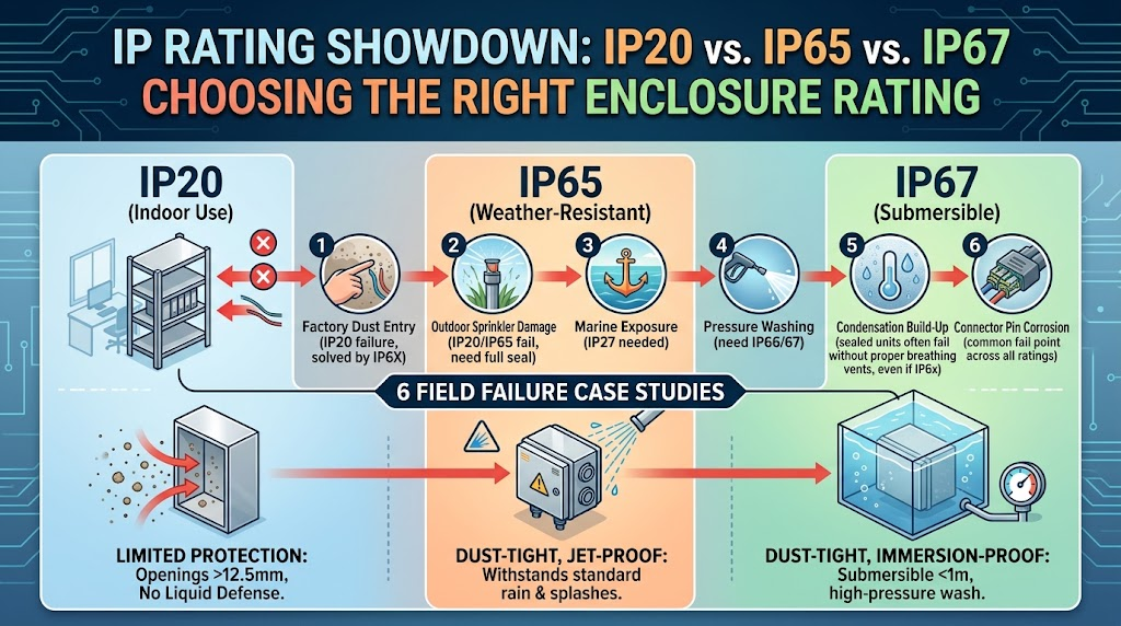
For potted IP67 outdoor units, push it to 30–50%: sealed construction sheds heat poorly and case temperature runs 15–25 °C higher at the same load. The rating side of that choice is covered in IP20 vs IP65 vs IP67: choosing an enclosure rating.
FAQ
Can a constant voltage supply drive bare LEDs? No — never. An LED is a current-driven device, and its forward voltage falls with temperature (roughly −2 mV/°C). Under constant voltage, current rises as it heats, which heats it further: thermal runaway until it burns. Bare LEDs need a constant current driver, or a series resistor / linear CC IC in the string.
How do I know whether I need CV or CC? Read the luminaire label. “Input DC24V” means CV. “Input 700 mA, voltage range xx–xx V” means CC. Finished tape, strips and modules are almost always CV. Bare-LED luminaires — spots, floods, high bay — are almost always CC.
How do I read a constant power driver’s window? Look for “constant power voltage range” or “output current range,” or just ask for the V-I curve. If the datasheet only says “250 W” with no range, the datasheet is deficient — a legitimate constant power driver always publishes the window.
Can I parallel two constant current drivers for more current? No. They fight each other, which shows up as flicker, hiccuping or repeated restart. Use one larger driver, or split the load into two groups with one driver each.
How far can I run 0–10 V dimming wires? No hard limit in the standard, but 50–100 m is the practical ceiling. 0–10 V is a current signal, and line resistance introduces drop — “10 V” at the panel may arrive as 8 V, so you can’t reach full brightness. Past 100 m, add a signal repeater or move to DALI.
How does PWM dimming compare to 0–10 V on flicker? Depends on the PWM frequency, not the interface. A 0–10 V driver is usually implementing PWM or analogue dimming internally anyway, so what matters is output ripple and dimming depth. PWM above 1 kHz and a well-built 0–10 V driver both land in the IEEE 1789 no-risk zone. A cheap 200 Hz design flickers regardless of what’s on the label.
Why does a constant current driver cost more than a constant voltage one at the same 150 W? CC needs precision current sensing and a tighter feedback loop: a low-ppm shunt resistor (a few milliohms, under 50 ppm/°C drift) and a more complex controller. The output voltage window is also a design cost — the wider the window, the harder the loop compensation.
Four checks before you order
- Read the luminaire input spec. “DC24V” or “700 mA” — this fixes CV or CC immediately
- Size with headroom. 20% indoors, 30–50% for potted outdoor
- If it’s constant power, check the window. Load voltage must sit inside it, or calculate the real power
- Confirm the dimming interface and its variant. Source or sink for 0–10 V, commissioning hours for DALI, frequency for PWM
Work those four and the 1,200-fixture scenario stops being a possibility.
Not sure which driver matches your fixture? Send the number of LEDs per string, string voltage and current, total power, ambient temperature at the install point and the dimming method, and talk to engineering — we’ll match it directly against the V-I curve and give you the calculated actual output power. For OEM volumes, custom constant power LED drivers can be built around your string configuration rather than the other way round.