How to Choose the Right 250W Indoor LED Driver 24V for Commercial Lighting Applications
Selecting the correct 250W indoor LED driver delivering a stable 24V DC output requires more than simply matching voltage and power ratings. In commercial installations—such as retail display cases, hospitality cove lighting, architectural accents, and linear LED aluminum channels—system reliability, thermal performance, total harmonic distortion (THD), and voltage drop over distance determine whether a project lasts five years without maintenance or fails within months.
This technical guide breaks down the engineering considerations, safety standards, and sizing calculations necessary to spec a 250W indoor LED driver 24V for high-duty commercial environments.
1. Electrical Performance Metrics: Beyond Voltage and Wattage
When matching a 24V LED driver to high-density LED strips (such as COB or 2835 SMD arrays running at 14.4W/m to 24W/m), system designers frequently overlook electrical quality metrics that directly impact continuous operation.
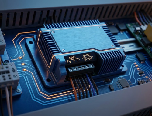
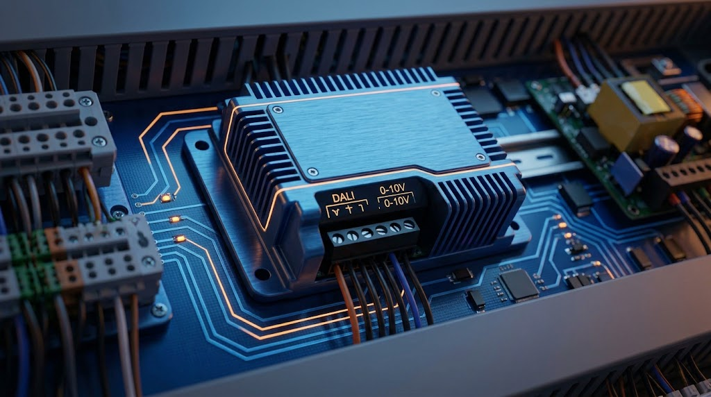
From raw AC utility grid feed to stabilized low-voltage LED distribution, the power conversion architecture follows four discrete electrical stages:
-
Stage 1: AC Mains Input (100–240V Universal Input)
-
Connects directly to facility panel breakers with over-voltage transient protection.
-
-
Stage 2: Input Protection & EMI Filtering
-
Integrated Active Power Factor Correction (Active PFC with ).
-
Total Harmonic Distortion suppression () to eliminate line interference with audio/visual systems.
-
-
Stage 3: Switching Regulation & Thermal Dissipation
-
Half-bridge LLC resonant switching topology producing regulated Constant Voltage ().
-
Heavy-duty extruded aluminum enclosure for passive convection cooling.
-
-
Stage 4: 24V DC Output Distribution (10.4A Maximum Capacity)
-
Branch A: High-density COB/SMD LED strip arrays (calculated using the continuous 80% load rule).
-
Branch B: Architectural linear aluminum profiles and recessed cove channels.
-
Power Factor (PF) and Total Harmonic Distortion (THD)
Commercial buildings enforce strict power quality codes. An industrial-grade driver must feature Active Power Factor Correction (Active PFC) with a PF at full load. High power factor minimizes reactive power drawn from the building’s electrical grid, preventing line penalties from utility providers.
Equally critical is Total Harmonic Distortion (THD). Cheap commercial power supplies often exhibit THD levels exceeding 30%, which introduces electrical noise into nearby audio/visual equipment and overloads neutral conductors. Aim for drivers rated at THD < 15% (or < 10% for noise-sensitive environments like broadcasting studios and corporate boardrooms).
Inrush Current Management
When a 250W power supply powers on, its input decoupling capacitors instantly charge, creating a momentary spike called inrush current. A single driver may draw up to 60A for a few milliseconds.
If you switch 10 to 15 drivers simultaneously on a single 16A Circuit Breaker (MCB), the combined inrush spike will trip Type C or Type B breakers. Ensure your selected driver incorporates an internal NTC thermistor or soft-start circuit to limit peak inrush current below 40A.
2. Deciphering Ingress Protection: Why IP20 Matters for Indoor Spaces
Ingress Protection (IP) ratings define how well an electrical enclosure resists solid objects and liquids. For indoor applications, understanding the trade-offs between IP20, IP44, and IP67 drivers prevents over-specifying and unnecessary thermal build-up.
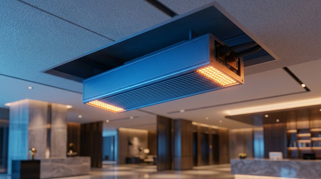
An IP20 LED Driver features a ventilated metal shell designed for passive air cooling inside dry drop ceilings, electrical closets, junction boxes, and display cabinets. Because IP20 units omit heavy epoxy potting, they operate cooler under standard indoor airflow conditions, reducing thermal stress on internal electrolytic capacitors.
If your installation involves high humidity—such as commercial kitchens, indoor swimming facilities, or cold-chain display cases—opt for an IP67 sealed unit instead. For standard dry indoor fit-outs, an IP20 driver provides maximum thermal longevity at optimal cost efficiency.
3. De-Rating Rules and Current Calculations for a 250W Load
Running a switching power supply at 100% capacity continuously in a closed architectural void accelerates thermal degradation. Electrolytic capacitors degrade exponentially faster for every rise in operating temperature (known as Arrhenius’ Law).
Applying the 80% Load Rule
To guarantee system stability and extended service life (50,000+ hours), apply the standard 80% de-rating rule:
For a 24V DC Constant Voltage system, calculate maximum available output current as follows:
If your lighting layout requires running 180W total of COB LED tape (e.g., 12 meters of 15W/m tape), a single 250W Indoor LED Driver 24V handles this continuous 7.5A demand comfortably within the 80% thermal safety margin.
4. Preventing Voltage Drop in 24V DC Low-Voltage Runs
Low-voltage 24V systems experience higher voltage drop across wire runs compared to high-voltage AC lines. If the voltage delivered at the end of an LED strip drops below 22.5V DC, you will observe visible color shifting, uneven brightness, and premature LED diode failure.
Formula for Voltage Drop:
V_drop = (2 * L * I * R) / 1000

Where:
L = Run Distance in meters (one-way)
I = Current in Amperes
R = Conductor Resistance in Ohms per 1000m
Copper Wire Gauge Selection Table (24V System, Max 3% Drop = 0.72V)
Recommendation: Keep the distance between the 250W driver output terminal and the start of the LED strip under 5 meters when using 16 AWG wire. For longer home-runs, step up conductor size to 14 AWG or split the continuous run into multiple parallel feeds powered from the central power unit.
5. Benchmarking Model Specs: The PS600-H1V24 Series Architecture
When selecting industrial-grade switching power supplies for high-density indoor LED installations, analyzing specific board-level topology reveals why certain hardware handles continuous commercial stress better than off-the-shelf alternatives.
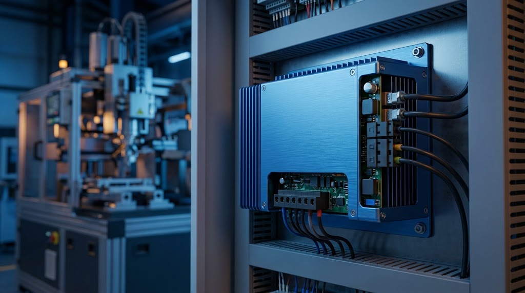
To achieve continuous 24/7 reliability in commercial builds, high-capacity single-rail units like the PS600-H1V24 Power Supply process electrical loads through an engineered half-bridge LLC resonant circuit:
-
AC Input Stage (100–240V AC): Passes through an onboard primary differential surge filter rated for spike protection.
-
Active PFC Stage: Dynamically adjusts phase alignment between current and voltage to keep input power factor above 0.95.
-
LLC Resonant Converter Stage: Converts high-voltage DC to high-frequency AC with zero-voltage switching (ZVS) to maximize energy conversion efficiency.
-
Synchronous Rectification & Safety Logic: Converts high-frequency AC into ripple-free while active logic monitors for output short-circuits or overload conditions.
-
Output Terminal Block: Delivers up to across heavy-gauge screw terminal connections.
This topology yields several practical installation advantages:
-
Conversion Efficiency : Minimizes internal heat dissipation, allowing the power unit to operate stably without loud cooling fans.
-
Hiccup Mode Overload Protection: Automatically recovers once short circuits or load overruns are cleared.
-
Over-Voltage Clamping: Prevents damaging voltage spikes from reaching sensitive LED chips if internal control loops break.
-
Thermal Shutdown: Triggers automatic shutdown if ambient enclosure temperatures exceed .
6. Installation & Thermal Management Checklist
Improper physical installation is the single primary cause of premature indoor driver failure. Follow this field installation protocol:
Mounting Orientation and Thermal Clearance Requirements
-
Vertical Alignment: Mount the metal housing vertically with output terminal blocks facing downward. Vertical mounting uses natural convection currents to move ambient air up through the side vents, lowering internal capacitor temperatures by to compared to flat horizontal placement.
-
No Direct Insulation Contact: Never cover ventilated IP20 casings with ceiling insulation blanket materials. Maintain a thermal buffer box when installing within drop-ceiling cavities.
-
Primary AC Grounding: Always connect the protective earth (PE) ground wire to the driver’s ground terminal. Grounding drains stray electromagnetic interference (EMI) and prevents high-frequency floating voltages on the 24V DC negative rail.
-
Wire Ferrule Crimping: Strip stranded DC output cables clean and crimp insulated wire ferrules before securing them into terminal block screw clamps. Loose wire strands cause localized high-resistance hot spots that melt terminal blocks under 10A continuous loads.
7. System Troubleshooting Matrix
If problems occur during commissioning, use this diagnostic matrix to isolate electrical faults quickly:
Technical Summary & Procurement Specifications
When specifying a 250W indoor 24V power supply for commercial lighting projects, insist on these minimum baseline parameters on your engineering submittal sheets:
-
Topology: Constant Voltage (24V DC)
-
Rated Output Current: 10.4A (Maximum)
-
Input Range: 100–240V AC (Universal)
-
Power Factor: at full load
-
Efficiency:
-
Protections: Short-circuit, Overload, Over-voltage, Over-temperature
-
Safety Certifications: CE, RoHS, UL/ETL Listed (or EN61347 compliant)
To review technical datasheets, CAD dimensional drawings, or request sample units for engineering evaluations, visit the official product page for the 250W Indoor LED Driver 24V or contact our engineering support team directly.